Blog

First Contact: October 29, 2016

With the antenna up, we finally got coax and rotor cables run, and an Icon-746 transmitter set up Saturday morning October 29.  After admiring the SWR from 10 to 30 MHz. (it was low), we rotated the beam and noted that it was directive as hoped.

The phone bands were alive with a contest.  We were surprised to hear significant activity as high in frequency as the 10 meter band.  There had been a coronal mass ejection from the sun a couple of days earlier, and perhaps that affected the ionospheric propagation.

Our first contact was with Dave Kerns’ dad in Illinois.  Dave had alerted his dad via telephone that we were set up to operate on a particular frequency, and contact was immediately established by Dave.  Then everyone got to say hello.  Dave’s dad, a long-time ham, was apparently using a metal drain pipe as an antenna.

The morning concluded with a cookout on our new grill with hamburgers and hot dogs.

Later in the day Eric Gustason stopped by and explained some of the more obscure controls on my Icom-746 transceiver.  In the process, I measured the transmitter’s output power to be only 2 watts!  This was the power level we were using in the morning.  After turning a tiny knob on the transmitter’s front panel, the peak power read 100 watts.  THEN stations started to answer my calls and we worked a contest station on an island off the coast of Brazil.

Dave Kerns made a video of the antenna being raised from telescoped to extended position but so far it has been “too big” for me to insert into this blog.  Below are several pictures taken by Anu Condon.

img_2193  Here are (left to right) Bob Condon, Dave Kerns and Mike Parker watching Lyle Johnson explain how to run the Icon-746 transceiver.

img_2207
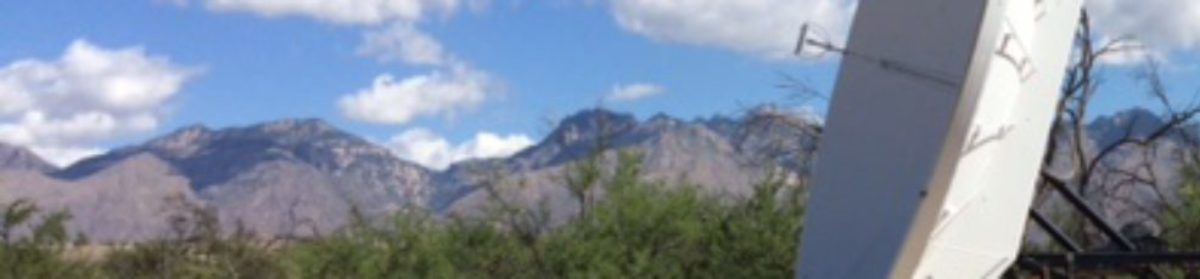
Ready to raise the antenna.

img_2210Pushing the UP button

and hoping nothing drops on top of us.

Antenna is Up

The antenna is complete and mounted on the tower  A sweep of SWR across the HF bands made from the base of the tower looks good.

The tower has been raised and lowered.  The antenna has been rotated from the base of the tower.  Cables have been buried to the house, but not yet tested from the house.

A first contact party is planned for Saturday, Oct. 29.  Start about 8:30 AM.  Hamburgers, hot dogs, chips, etc. will be cooked for lunch.

Thanks to Bob Condon for help putting on antenna elements and the iPhone photos.

picframe


Distance & Type of Cable Runs

1. Distance

  • 216 ft house to trailer
  • 72 ft trailer to tower base
  • 74 ft base to tower top + 6 ft wrap allowance = 80 ft base to antenna

2. Cable Types

2.1 Initial Cables

  1. HF transmit coax house to tower base.  335 ft.:  Low loss 50 ohm with >3 kW power capability.  Should be direct burial.  (Ordered 1/2″ Heliax LDF4-50A with PL-259 connectors)
  2. HF transmit coax tower base to antenna, 80 ft:  Low loss 50 ohm flexible with > 2 kW power.
  3. HF antenna rotor, 415 ft total:  4 wires (2 large wires for motor and 2 smaller wires for rotation sensor counter).  Run from house to tower base should be direct burial. (cable in conduit)  Purchased:Wireman part # 305 Rotor cable 2×12 and 2×16 Quantity 500 ft  @ 0.715 / ft = 357.50
  4. Tower raise/lower control, 70 ft trailer to tower base: 6 wires: Direct burial.  (cable in conduit)
  5. 120 vac extension cord, 50 ft, from power pedestal to tower base for tower raise/lower.
  6. Ethernet cat 6 direct burial cable 216 ft from house to trailer for computer data and control.  (cable in conduit)
  7. 2nd low-loss 50 ohm coax house to trailer, 216 ft.  Direct burial.  For future expansion, but put into trench initially due to difficulty in pulling big/stiff cable at later stage.  Possibly used to feed HF wire antennas.  (Ordered 1/2″ Heliax with type N connectors)

2.2 Future Cables in House-to-Trailer Conduit

  1. VHF/UHF moderate loss (~10 db) house to trailer 270 ft:  Assumes Linear amp/LNA combo is either in trailer or mounted at antenna with transceiver in house.
  2. Many-conductor rotor cable for Az/El control of VHF/UHF antennas (or control may be via ethernet from house to trailer)

  3. TBD timing cable(s).  Possibly moderate loss @ 10 MHz.

  4. TBD control of Microwave antenna Az-El

  5. TBD Coax house to trailer for use of microwave gear with moderate loss at TBD IF frequency.

3. Coax notes

Coax Cable Notes from Times-Microwave
     LMR – Flexible Low Loss
     LMR-DB  Watertight   -Flexible Low Loss
     LMR-Ultraflex    -Repeated flexing
     LMR400 Ultraflex 0.5 dB/100 ft @ 10 MHz, 0.8 dB/100ft @ 30 MHz
     LMR400-dB     0.7 dB/100ft @ 30 MHz.
     LMR600-dB    0.4 dB/100 ft @ 30 MHz.
     LMR600-UF    0.5 dB / 100 ft @ 30 MHz
Other Notes
     Bury-flex davis RF buy from the Wireman part #103A $0.85/ft 0.6 dB/100ft @ 10 MHz, 1.1 dB/100ft @ 50 MHz.,
          Do not bury PVC jackets.  Use PE jacket.
     CQ “super 8’ part #106 0.8 dB/100 ft @ 30 MHz.
     CQ 113PE  0.8 dB/100 ft @ 30 MHz
Heliax (formerly by Andrew, now Commscope) and appears to have competitors although heliax is trademarked.
       3/8″ LDF2-50  0.56 dB/100ft @ 30 MHz
       1/2″  LDF4-50  0.36 dB/100 ft @ 30 MHz
      5/8″  LDF4.5-50 0.254 dB/100 ft @ 30 MHz
      7/8″  AVA5-50FX 0.191 dB/100ft @ 30 MHz
Issues:  Connectors & attachments
      To put connectors on heilax see
           www.davisrf.com/articles/Heilax-Instll-Tips.pdf
           I ordered connectors on cable.
      To assemble Amphenol 83-1SP (PL-259 UHF for BuryFlex, etc)  see
           www/davisrf.com/articles/Amphenol-Install-83-1SP.pdf

4. Sources

davisrf.com
www.thewireman.com
dxengineering.com
theantennafarm.com
rfparts.com
L-com.com
thedxshop.com (England but has useful web site for heliax
www.timesmicrowave.com (LMR coax)
Andrews or commscope makes heliax